Thermistor mystery

I was working with some thermistors for a recent project, I’m making a WiFi fridge sensor that sends data via MQTT, anyway, it uses a thermistor as the temp sensor and the ones I got did not come with a good datasheet. The datasheet for my part did not include any data on the temperature/resistance curve! Most good thermistors will come with the curve information in their datasheets and infact some will even include the Steinhart-Hart coefficients, but this did not. The part in question is a Cantherm MF52A2103J3470 and I had to figure out the curve on my own.

The process that I followed was to use a thermocouple I had connected to a multimeter to get known temperatures and then use another multimeter to check the resistance of the thermistor at those known temperatures. I ended up grabbing the following data points:

-26C = 96.3K
+4 = 24.1K
+39 = 5.5K

Once I had those datapoints I could drop them into this thermistor calculator: https://www.thinksrs.com/downloads/programs/therm%20calc/ntccalibrator/ntccalculator.html

The calculator then produced the following coefficients for the Steinhart-Hart equation:

A=1.221849189e-3
B=2.094372171e-4
C=2.785700391e-7

With those coefficients I was able to calibrate my thermistor to a reasonable level of accuracy!

PastaCode Broken Snippets

It turns out that PastaCode, the syntax highlighting plugin I use is no longer being updated, doesn’t work with this version of WordPress and mangled all of my code so I’ll have to go through my old posts and see if I can replace the broken code and run it through my new syntax Highlighter CodeColorer, it’ll take some time before I can get all the snippets back up, sorry for the inconvenience.

Laser cutter/Engraver add-on for 3D printer

A while back I was mulling over the idea of a laser engraved PCB etching process and I found a 2.5 Watt cutting laser diode on sale for cheap on Banggood and decided to go for it, many months later I finally managed to get around to testing it and the laser works great! I decided that the obvious thing to do with the laser would be to attach it to my 3D printer as a removable module so that I could have 3D printing and laser cutting/engraving all in one machine instead of having to build another motion platform.

The 3D printer I’m using is a heavily modified Geeetech i3 Pro C kit that I assembled a few years ago, since getting the kit I have upgraded the hotend to an E3D V6 using this extruder assembly. The extruder works great and best of all it has lots of attachment points built in, which made adapting the laser very simple.

I made up a bracket in OnShape to mount the laser to the front of the extruder, printed it and bolted it on and slid the laser into the mount. I added a connector to the wiring of my layer cooling fan and added a mating connector to the laser so that I could use the fan PWM (which I recently upgraded to a 5A MOSFET) to control the laser.

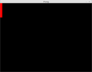
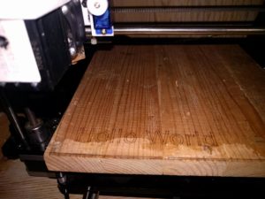
I donned my laser goggles and turned the laser up to 30% power, focused the beam as close to perfect as I could by eye and started checking the new zero point I would have to use for the laser. With my new zero point determined, I started looking into my laser etching process, the first test was a simple “Hello World” engraving into a piece of wood to verify my settings and focal point. I used Inkscape with the J Tech Photonics plugin and it worked great with no issues, it’s a great plugin for outlining vector shapes!

With the first test completed, I decided to look into the PCB etching process, the usual way that this is done is to paint the board with a light coat of matte black paint, take the board layout from the CAD software, generate an image of the paths, make it a black and white negative, raster burn that onto the board and then etch the result, this works, but it’s not very precise and it’s not very fast, the laser ends up doing a lot of extra moves and diagonal lines tend to end up with a lot of aliasing.

To get around these issues, I decided to take my board design from Eagle, run it through the isolation milling plugin PCB-GCODE, modify the resulting gcode to replace all spindle motion in the z axis with laser on/off commands and then go through the normal process of paint, engrave and etch.

Setting up PCB-GCODE was fairly straightforward, I just setup the machine settings to match my 3D printers capabilities, set the cutter diameter to the approximate laser spot size, set the isolation step to half of the spot size and set the Z up and Down parameters to 0 and 1 so I could easily parse them later with a script. I ran the resulting gcode through NC Viewer to validate the tool paths and kept tweaking the machine settings until I was satisfied with what I was seeing in the simulation, at this point it was on to scripting.

I decided to use Python to do the processing for no other reason than I hadn’t done any Python scripting before and I wanted to give it a try. I was able to find some simple example code that showed how to find and replace data in a file and modified that to take in the gcode file and replace and remove the elements I needed to change, in this case:

G00 Z0.0000 became M106 S255
G01 Z1.0000 F6000.00 became M107
M02, M03 and M05 were removed

and the following code was injected after the last comment in the file header to home the axes and set the new zero location for the file to start at:

G28 ;Home all axes
G0 X0 Y46 Z47.5 ;Move to laser Zero position
G92 X0 Y0 Z0 ;Zero X,Y and Z

After all this I have a basic tool chain assembled for the PCB laser etch process, the only things left to do are to do a few test runs on paper to validate the beam width settings, do some tests on painted copper to determine the necessary cut speed for ablating the paint and then try it on a real board to see what kind of results can be had! So far, it looks promising and should be much faster and more precise than raster engraving, it’s also worth mentioning that it should use far less etching chemicals than the conventional methods! of course in order to continue I will need to hook up a fan to clear the smoke away from the laser and figure out a ventilation system to vent the fumes outdoors rather than into my office, but we’ll get their in time.

Mapping a small sensor range to full ADC range

Today I decided to look into a more elegant solution to the problem of accurately determining the angle of my rudder pedals, previously I had solved this problem with a mechanical solution that converted the specific degrees of rotation of the rudder pedal cross arm to the 270° rotation of the potentiometer I’m using. This mechanical solution involved a timing belt and two 3D printed toothed wheels of the correct ratio.

There’s supposed to be some pictures here, but WordPress is currently broken for me 🙁

While this solution did work, it was not a particularly elegant solution and made calibration difficult as well as ran the risk of damaging the pot or causing the calibration to drift if the axis was forcibly pushed past it’s limits, which is very likely with a foot operated device!

The electrical solution I came up with was to use an Op Amp to map the output range of the sensor to the larger range of the Analog to Digital Converter so that I could use the limited motion of the potentiometer directly coupled to the rudder pedal cross arm and still get the full 0-5v range I was looking for to get the maximum precision from my ADC.

In my research for this solution I didn’t really know what I was looking for, I’m not an engineer of any description, nor do I possess a particularly strong grasp of mathematics or electronics theory, and so I frequently have to look things up, which is difficult when you don’t know how to phrase your question!

I stumbled my way across this thread on the electronics Stack Exchange:  where the original poster was looking to do something similar to myself and it provided a link to a Texas Instruments reference document on calculating the gain and offset of an Op Amp: Designing Gain and Offset in Thirty Seconds.

After parsing the formulas I entered them into a spreadsheet and began testing my results with TinkerCAD circuits, an excellent tool for testing circuits without blowing up any real world components! The circuit I came up with, with the help of the spreadsheet was this.

Please note that if you attempt to use the spreadsheet and it gives you crazy values, it may be that I made an error in the formulas, I have only tested the Positive m and Negative b function, as that is the one that is pertinent here. If you find any bugs and make a fix, please let me know so I can update the sheet!

This effectively reproduces the the scenario of a pot with limited range and swings the values between roughly 0 and 5v, which in this case was just a set of arbitrary values that I decided to use for testing the spreadsheet. I had to tweak the value of R1 in order to get the range I wanted, which is described in the TI reference.

So to sum it up, if you have a sensor that outputs a non-ideal range of voltages you can use an Op Amp to map that to a usable range and you can use TI’s helpful “Designing Gain and Offset in Thirty Seconds” to get you there, though the title is a little optimistic unless you already know what you’re doing!

Capturing a time lapse from a Raspbery Pi camera

After running into a bug with VLC capturing images from an RTSP stream in Linux, I decided to go a different route for capturing time lapses from my 3D printer and that was to use a local script on the PI that can be run with command line parameters to set the interval and duration of the capture and have the images output to a network share, this should satisfy the same goal as the RTSP stream by not having the PI store or write data to the SD card and so prolong its life

I went about the process in this order:

  • Setup a share on my workstation
  • On the pi “sudo apt-get install samba-common smbclient samba-common-bin smbclient cifs-utils”
  • Add the share to /etc/fstab by appending “//<server>/Timelapse /mnt/timelapse cifs guest,rw,iocharset=utf8,file_mode=0777,dir_mode=0777 0 0”
  • Reboot the Pi to ensure the mount is permanent

After that I wrote a simple script to allow for timelapse capture:

#!/bin/bash
#Timelapse from an RPi Camera
if [ $# == 0 ]
then
echo
echo “usage: $0 [runtime] [interval] [destination]”
echo
echo ‘All times are in seconds (3600 seconds per hour)’
echo
echo “example:  $0 3600 60 ~/images/timelapse”
exit
fi
runtime=$1
interval=$2
if [ $# -gt 2 ]
then
store_path=$3
else
store_path=/mnt/timelapse
fi
while [ $SECONDS -lt $runtime ]
do
datetime=$(date +”%FT%H%M%S”)
raspistill -vf -hf -o $store_path/$datetime.jpg
sleep $interval
done
echo ‘time lapse complete’

Unfortunately I ran into trouble where whenever calling raspistill I would get an ENOSPC error and it would fail to do any capturing, I ran a firmware update and that led me down a rabbit hole where it looks like the rpi-update is broken on older Pis such as my Rpi 1B, this required downloading the files manually and forcing the update without a download as per the below:

curl -L https://github.com/Hexxeh/rpi-firmware/archive/master.tar.gz -o master.tar.gz
cd /root/.rpi-firmware
sudo tar -xvzf /home/pi/master.tar.gz –strip-components=1
sudo SKIP_DOWNLOAD=1 rpi-update

Finally, with all of that complete I tried again and it failed, reason being I still had my streaming script running from the previous article! I went through and disabled the service I had setup previously:

systemctl disable stream-rstp.sh

And tested and successfully got an image off the camera, I tested my script, and it worked!

I can now grab high resolution time lapses of my 3D printer by SSHing into my Pi and running a single command string!


Capturing a time lapse from an RTSP Stream

I was looking for a better way to capture time lapse recordings of my 3D printer, Octopi on my old raspberry Pi just wasn’t cutting it, so I decided to setup an RTSP stream as per this post here by Chris Carey, that was straightforward enough, but then I needed a way to periodically grab frames from the camera as it streamed, for this, VLC came to the rescue! With a (relatively) simple command line I’m now able to grab frames and encode them in JPG format and those can in turn be recombined into a time lapse video!

The command I used was a follows:

“C:\Program Files (x86)\VideoLAN\VLC\vlc” rtsp://192.168.254.202:8554/stream -V dummy –intf=dummy –dummy-quiet –video-filter=scene –no-audio –scene-path=C:\temp –scene-format=jpeg –scene-prefix=snap-%datetime% –no-scene-replace –run-time=1 vlc://quit

I used a little batch trickery to get the filename to include the current date and time via this handy little addendum:

for /f “tokens=2 delims==” %%I in (‘wmic os get localdatetime /format:list’) do set datetime=%%I
set datetime=%datetime:~0,8%-%datetime:~8,6%

And that’s it, just run that as a scheduled task and you have periodic screen grabs!

I’ll be working on converting this to Linux later on, which should be pretty simple, but for now I’m working on a Windows machine so that’s what I have for now.

Youtube Settings for KDENLIVE


I’ve been working with KDENLIVE recently and trying to get a good result for YouTube, unfortunately while KDENLIVE is very powerful, it’s documentation is abysmal, most of it is out of date and none of it explains the syntax that should be used for the render profiles, the format is pretty esoteric and really hard for a neophyte to parse.

So far I have been able to gather that the following settings seem to do the trick:

codec:v libx264 crf 21 bf 2 -flags +cgop pix_fmt yuv420p codec:a aac -strict -2 b:a 384k r:a 48000 -movflags=+faststart -fps 60

Here are the parts I understand:

codec:v libx264 -> Set the Video codec to H.264
codec:a aac -> Set the Audio codec to AAC
r:a 48000 -> Set audio sample rate to 48000
-movflags=+faststart -> Sets the moov atom at the front of the file (Fast Start)
-FPS 60 -> set the FPS to 60

The rest I’m not too sure about, but it seems to produce good looking video, if anyone can explain the remaining settings, I’d be interested to learn!

Linux Mint Screen Tearing with Mate and Nvidia

Recently I switched over to using Mate as my window manager due to some lag issues with Cinnamon and I’ve been having issues with screen tearing since the switch, the vsync setting in the Nvidia control panel doesn’t appear to help. I found an interesting solution on CMSCritic.com that showed how to correct this, and testing showed that it worked, but only for one monitor. Problematically, I have three monitors, so I had to take apart this command they used and see if I could rearrange it to work with my setup.

The original command they suggested was:

nvidia-settings –assign CurrentMetaMode=”nvidia-auto-select +0+0 { ForceCompositionPipeline = On }”


Doing this turned off my other two monitors but did take care of the screen tearing on the remaining monitor, so I went into the Nvidia control panel, generated an xorg.conf file and inspected the settings there, I found this line:

Option         “metamodes” “HDMI-0: nvidia-auto-select +0+72, DVI-D-0: nvidia-auto-select +1920+0, DVI-I-0: nvidia-auto-select +3968+72″


This looks very familiar, so by taking the information in that line and rearranging it into the command before we get:

nvidia-settings –assign CurrentMetaMode=”HDMI-0: nvidia-auto-select +0+72, DVI-D-0: nvidia-auto-select +1920+0, DVI-I-0: nvidia-auto-select +3968+72 { ForceCompositionPipeline = On }”


Nothing appeared to change at first when I ran this, but it did solve the screen tearing problem, but only on the third monitor! So what we learned here is that the ForceCompositionPipeline command is display independent. I rearranged the command one more time and came up with this:

nvidia-settings –assign CurrentMetaMode=”HDMI-0: nvidia-auto-select +0+72, DVI-D-0: nvidia-auto-select +1920+0 { ForceCompositionPipeline = On }, DVI-I-0: nvidia-auto-select +3968+72″


This runs that command against only my center monitor, which is my primary. After testing the command by running Deus Ex: Mankind Divided, I determined there there is no performance impact from enabling this command, which is excellent news! I modified the command one last time to apply the affect to all of my monitors:

nvidia-settings –assign CurrentMetaMode=”HDMI-0: nvidia-auto-select +0+72 { ForceCompositionPipeline = On }, DVI-D-0: nvidia-auto-select +1920+0 { ForceCompositionPipeline = On }, DVI-I-0: nvidia-auto-select +3968+72 { ForceCompositionPipeline = On }”


I tested again with Deus Ex: Mankind Divided, and again determined that there was no impact on frame rate so now I can integrate this with my xorg.conf and enjoy my system without having to endure terrible screen tearing!

Game Design

Now is a good time to start thinking about the nuts and bolts of our game and how we’re going to make it all work. We can think of our game as a series of things with “is a” and “has a” relationships, we’ll probably want something like this:

  • A Game class that has:
    • A game state enum
    • A method for changing game states
    • A method for restarting the game
    • A Ball class
    • A Player class
    • A playing field or level
    • A win condition that ends the game
  • Ball class that has:
    • An X,Y position
    • An X,Y velocity
    • An image
    • A method for Collision Detection
  • A Player class that has:
    • A score
    • An SDL_Rect
    • A method for getting points

We can start building out our classes and adding functionality as we go. We’ll ignore the state machine that we implemented earlier so that we can focus on getting stuff on the screen, once we have stuff on the screen we can worry about states and what they will do.

The Player class is a good place to start since it’s very simple and will allow us to get something on the screen. An SDL_Rect has a height and width as well as an x,y position, so adding the SDL_Rect means we don’t need a separate set of position variables, we can just use those. So far our player class looks like this:

[pastacode lang=”cpp” manual=”%23ifndef%20PLAYER_H%0A%23define%20PLAYER_H%0A%0A%23include%20%3CSDL2%2FSDL.h%3E%0A%0Aclass%20Player%0A%7B%0A%20%20%20%20public%3A%0A%20%20%20%20%20%20%20%20Player()%3B%0A%0A%20%20%20%20%20%20%20%20void%20AddScore(int)%3B%0A%20%20%20%20%20%20%20%20int%20GetScore()%7Breturn%20score%3B%7D%3B%0A%20%20%20%20%20%20%20%20void%20Update()%3B%0A%20%20%20%20%20%20%20%20SDL_Rect*%20GetPaddle()%7Breturn%20%26paddle%3B%7D%3B%0A%0A%20%20%20%20private%3A%0A%20%20%20%20%20%20%20%20int%20score%3B%0A%20%20%20%20%20%20%20%20SDL_Rect%20paddle%3B%0A%0A%7D%3B%0A%0A%23endif%20%2F%2F%20PLAYER_H%0A” message=”Player.h” highlight=”” provider=”manual”/]

[pastacode lang=”cpp” manual=”%23include%20%22player.h%22%0A%0APlayer%3A%3APlayer()%0A%7B%0A%20%20%20%20%20%20%20%20score%20%3D%200%3B%0A%20%20%20%20%20%20%20%20paddle.x%20%3D%200%3B%0A%20%20%20%20%20%20%20%20paddle.y%20%3D%200%3B%0A%20%20%20%20%20%20%20%20paddle.h%20%3D%20100%3B%0A%20%20%20%20%20%20%20%20paddle.w%20%3D%2015%3B%0A%7D%0A%0Avoid%20Player%3A%3AAddScore(int%20s)%0A%7B%0A%20%20%20%20score%20%2B%3D%20s%3B%0A%7D%0A%0Avoid%20Player%3A%3AUpdate()%0A%7B%0A%0A%7D%0A” message=”” highlight=”” provider=”manual”/]

We can make the player paddle object show up by instantiating a Player object called P1 and adding the following to the render sequence:

[pastacode lang=”cpp” manual=”SDL_SetRenderDrawColor(renderer%2C%200%2C%200%2C%200%2C%20255)%3B%0ASDL_RenderClear(renderer)%3B%0ASDL_SetRenderDrawColor(renderer%2C%20255%2C%200%2C%200%2C%20255)%3B%0ASDL_RenderFillRect(renderer%2C%20P1.GetPaddle())%3B%0ASDL_RenderPresent(renderer)%3B” message=”” highlight=”” provider=”manual”/]

And with that we get this:

Not terribly exciting yet, but this is a start! It’s a simple matter now to instantiate another player and add the ball class, after that we are into game logic and we’re basically done! We’ll get more done on the next entry!

Re-architecting

Now that we’ve made this much progress, it might be time to consider re-working the code to actually do something, this might actually be something that is better left to another github repo so we can keep using this one as a testing ground for ideas.


I think what we’ll do now is take what we’ve learned messing with physics and try to make a game, a Pong clone seems like the obvious choice to get started considering the subject matter thus far, there will be problems to overcome, but I think we’re well equipped to sort them out!

The new repo is https://github.com/Atrixium/pong and we’ll set up our initial commit now.


The first thing we need to do is include SDL, SDL_image and SDL_ttf and get a window open and ready, that means we need to:

  • Modify the build options to link to SDL2, SDL2_image and SDL2_ttf
  • Initialize SDL video and audio subsystems
  • Create a Window
  • Create a Renderer

[pastacode lang=”cpp” manual=”%23include%20%3Ciostream%3E%0A%23include%20%3CSDL2%2FSDL.h%3E%0A%23include%20%3CSDL2%2FSDL_image.h%3E%0A%23include%20%3CSDL2%2FSDL_ttf.h%3E%0A%0A%0Aint%20main(int%20argc%2C%20char%20*argv%5B%5D)%0A%7B%0A%20%20%20%20if(%20SDL_Init(SDL_INIT_VIDEO%20%7C%20SDL_INIT_AUDIO)%20!%3D0%20)%0A%20%20%20%20%7B%0A%20%20%20%20%20%20%20%20std%3A%3Acout%20%3C%3C%20%22SDL%20Init%20Failed!%20%22%20%3C%3C%20SDL_GetError()%20%3C%3C%20std%3A%3Aendl%3B%0A%20%20%20%20%20%20%20%20return%201%3B%0A%20%20%20%20%7D%0A%0A%20%20%20%20if(%20IMG_Init(IMG_INIT_PNG)%20!%3D%20IMG_INIT_PNG%20)%0A%20%20%20%20%7B%0A%20%20%20%20%20%20%20%20std%3A%3Acout%20%3C%3C%20%22SDL_Image%20Init%20Failed!%20%22%20%3C%3C%20IMG_GetError()%20%3C%3Cstd%3A%3Aendl%3B%0A%20%20%20%20%20%20%20%20SDL_Quit()%3B%0A%20%20%20%20%20%20%20%20return%201%3B%0A%20%20%20%20%7D%0A%0A%20%20%20%20if(%20TTF_Init()%20!%3D%200%20)%0A%20%20%20%20%7B%0A%20%20%20%20%20%20%20%20std%3A%3Acout%20%3C%3C%20%22SDL_TTF%20Init%20Failed!%20%22%20%3C%3C%20TTF_GetError()%20%3C%3C%20std%3A%3Aendl%3B%0A%20%20%20%20%20%20%20%20IMG_Quit()%3B%0A%20%20%20%20%20%20%20%20SDL_Quit()%3B%0A%20%20%20%20%20%20%20%20return%201%3B%0A%20%20%20%20%7D%0A%0A%20%20%20%20SDL_Window*%20window%20%3D%20SDL_CreateWindow(%22Pong%22%2C%20SDL_WINDOWPOS_CENTERED%2C%20SDL_WINDOWPOS_CENTERED%2C%20640%2C%20480%2C%200)%3B%0A%20%20%20%20if%20(!window)%0A%20%20%20%20%7B%0A%20%20%20%20%20%20%20%20std%3A%3Acout%20%3C%3C%20%22SDL%20Window%20Creation%20Failed!%20%22%20%3C%3C%20SDL_GetError()%20%3C%3C%20std%3A%3A%20endl%3B%0A%20%20%20%20%20%20%20%20TTF_Quit()%3B%0A%20%20%20%20%20%20%20%20IMG_Quit()%3B%0A%20%20%20%20%20%20%20%20SDL_Quit()%3B%0A%20%20%20%20%20%20%20%20return%201%3B%0A%20%20%20%20%7D%0A%20%20%20%20SDL_Renderer*%20renderer%20%3D%20SDL_CreateRenderer(window%2C%20-1%2C%20SDL_RENDERER_PRESENTVSYNC)%3B%0A%20%20%20%20if(!renderer)%0A%20%20%20%20%7B%0A%20%20%20%20%20%20%20%20std%3A%3Acout%20%3C%3C%20%22SDL%20Renderer%20Creation%20Failed!%20%22%20%3C%3C%20SDL_GetError()%20%3C%3C%20std%3A%3A%20endl%3B%0A%20%20%20%20%20%20%20%20TTF_Quit()%3B%0A%20%20%20%20%20%20%20%20IMG_Quit()%3B%0A%20%20%20%20%20%20%20%20SDL_DestroyWindow(window)%3B%0A%20%20%20%20%20%20%20%20SDL_Quit()%3B%0A%20%20%20%20%20%20%20%20return%201%3B%0A%20%20%20%20%7D%0A%0A%20%20%20%20SDL_RenderClear(renderer)%3B%0A%20%20%20%20SDL_RenderPresent(renderer)%3B%0A%0A%20%20%20%20SDL_Delay(2000)%3B%0A%0A%0A%20%20%20%20%2F%2FCleanup%0A%20%20%20%20SDL_DestroyRenderer(renderer)%3B%0A%20%20%20%20SDL_DestroyWindow(window)%3B%0A%20%20%20%20IMG_Quit()%3B%0A%20%20%20%20TTF_Quit()%3B%0A%20%20%20%20SDL_Quit()%3B%0A%7D%0A” message=”” highlight=”” provider=”manual”/]

With this start code, we now have a cleared black window on the screen and we can setup the event handler and the render loop:

[pastacode lang=”cpp” manual=”%2F%2Fstart%20render%20loop%0A%0A%20%20%20%20bool%20quit%20%3D%20false%3B%0A%0A%20%20%20%20while(!quit)%0A%20%20%20%20%7B%0A%0A%20%20%20%20%20%20%20%20%2F%2Fstart%20event%20handler%0A%0A%20%20%20%20%20%20%20%20SDL_Event%20event%3B%0A%0A%20%20%20%20%20%20%20%20while(%20SDL_PollEvent(%26event)%20)%0A%20%20%20%20%20%20%20%20%7B%0A%20%20%20%20%20%20%20%20%20%20%20%20switch(event.type)%0A%20%20%20%20%20%20%20%20%20%20%20%20%7B%0A%20%20%20%20%20%20%20%20%20%20%20%20case%20SDL_QUIT%3A%0A%20%20%20%20%20%20%20%20%20%20%20%20%20%20%20%20%20%20%20%20quit%20%3D%20true%3B%0A%20%20%20%20%20%20%20%20%20%20%20%20%20%20%20%20%20%20%20%20break%3B%0A%20%20%20%20%20%20%20%20%20%20%20%20case%20SDL_KEYDOWN%3A%0A%20%20%20%20%20%20%20%20%20%20%20%20%20%20%20%20switch(event.key.keysym.sym)%0A%20%20%20%20%20%20%20%20%20%20%20%20%20%20%20%20%7B%0A%20%20%20%20%20%20%20%20%20%20%20%20%20%20%20%20%20%20%20%20case%20SDLK_q%3A%0A%20%20%20%20%20%20%20%20%20%20%20%20%20%20%20%20%20%20%20%20quit%20%3D%20true%3B%0A%20%20%20%20%20%20%20%20%20%20%20%20%20%20%20%20%20%20%20%20break%3B%0A%20%20%20%20%20%20%20%20%20%20%20%20%20%20%20%20%7D%0A%20%20%20%20%20%20%20%20%20%20%20%20%7D%0A%20%20%20%20%20%20%20%20%7D%0A%0A%0A%20%20%20%20%20%20%20%20SDL_RenderClear(renderer)%3B%0A%20%20%20%20%20%20%20%20SDL_RenderPresent(renderer)%3B%0A%0A%20%20%20%20%7D%2F%2F%20end%20main” message=”” highlight=”” provider=”manual”/]

Now clicking the x or pressing ‘q’ will close the window.


Next up we should work on a state machine that will track our games current state, allowing us to perform different actions in different modes such as going from a menu state to a playing state. We’ll implement this with a simple enum and a switch statement:

[pastacode lang=”cpp” manual=”%20%20%20%20%2F%2Fstart%20render%20loop%0A%0A%20%20%20%20while(gameState%20!%3D%20STATE_QUIT)%0A%20%20%20%20%7B%0A%20%20%20%20%20%20%20%20%2F%2Fstart%20event%20handler%0A%0A%20%20%20%20%20%20%20%20SDL_Event%20event%3B%0A%0A%20%20%20%20%20%20%20%20%2F%2Freact%20to%20input%20based%20on%20game%20state%0A%20%20%20%20%20%20%20%20switch(gameState)%0A%20%20%20%20%20%20%20%20%7B%0A%20%20%20%20%20%20%20%20case%20STATE_MENU%3A%0A%20%20%20%20%20%20%20%20%20%20%20%20std%3A%3Acout%20%3C%3C%20%22Entered%20menu%20state%22%20%3C%3C%20std%3A%3Aendl%3B%0A%0A%20%20%20%20%20%20%20%20%20%20%20%20while(%20SDL_PollEvent(%26event)%20)%0A%20%20%20%20%20%20%20%20%20%20%20%20%7B%0A%20%20%20%20%20%20%20%20%20%20%20%20%20%20%20%20switch(event.type)%0A%20%20%20%20%20%20%20%20%20%20%20%20%20%20%20%20%7B%0A%20%20%20%20%20%20%20%20%20%20%20%20%20%20%20%20case%20SDL_QUIT%3A%0A%20%20%20%20%20%20%20%20%20%20%20%20%20%20%20%20%20%20%20%20%20%20%20%20gameState%20%3D%20STATE_QUIT%3B%0A%20%20%20%20%20%20%20%20%20%20%20%20%20%20%20%20%20%20%20%20%20%20%20%20break%3B%0A%0A%20%20%20%20%20%20%20%20%20%20%20%20%20%20%20%20case%20SDL_KEYDOWN%3A%0A%20%20%20%20%20%20%20%20%20%20%20%20%20%20%20%20%20%20%20%20switch(event.key.keysym.sym)%0A%20%20%20%20%20%20%20%20%20%20%20%20%20%20%20%20%20%20%20%20%7B%0A%20%20%20%20%20%20%20%20%20%20%20%20%20%20%20%20%20%20%20%20%20%20%20%20case%20SDLK_q%3A%0A%20%20%20%20%20%20%20%20%20%20%20%20%20%20%20%20%20%20%20%20%20%20%20%20gameState%20%3D%20STATE_QUIT%3B%0A%20%20%20%20%20%20%20%20%20%20%20%20%20%20%20%20%20%20%20%20%20%20%20%20break%3B%0A%0A%20%20%20%20%20%20%20%20%20%20%20%20%20%20%20%20%20%20%20%20%20%20%20%20case%20SDLK_1%3A%0A%20%20%20%20%20%20%20%20%20%20%20%20%20%20%20%20%20%20%20%20%20%20%20%20gameState%20%3D%20STATE_MENU%3B%0A%20%20%20%20%20%20%20%20%20%20%20%20%20%20%20%20%20%20%20%20%20%20%20%20std%3A%3Acout%20%3C%3C%20%22Changed%20to%20menu%20state%22%20%3C%3C%20std%3A%3Aendl%3B%0A%20%20%20%20%20%20%20%20%20%20%20%20%20%20%20%20%20%20%20%20%20%20%20%20break%3B%0A%0A%20%20%20%20%20%20%20%20%20%20%20%20%20%20%20%20%20%20%20%20%20%20%20%20case%20SDLK_2%3A%0A%20%20%20%20%20%20%20%20%20%20%20%20%20%20%20%20%20%20%20%20%20%20%20%20gameState%20%3D%20STATE_PLAYING%3B%0A%20%20%20%20%20%20%20%20%20%20%20%20%20%20%20%20%20%20%20%20%20%20%20%20std%3A%3Acout%20%3C%3C%20%22Changed%20to%20playing%20state%22%20%3C%3C%20std%3A%3Aendl%3B%0A%20%20%20%20%20%20%20%20%20%20%20%20%20%20%20%20%20%20%20%20%20%20%20%20break%3B%0A%20%20%20%20%20%20%20%20%20%20%20%20%20%20%20%20%20%20%20%20%7D%0A%20%20%20%20%20%20%20%20%20%20%20%20%20%20%20%20%7D%0A%20%20%20%20%20%20%20%20%20%20%20%20%7D%0A%20%20%20%20%20%20%20%20%20%20%20%20break%3B%0A%0A%20%20%20%20%20%20%20%20case%20STATE_PLAYING%3A%0A%20%20%20%20%20%20%20%20%20%20%20%20std%3A%3Acout%20%3C%3C%20%22Entered%20playing%20state%22%20%3C%3C%20std%3A%3Aendl%3B%0A%0A%20%20%20%20%20%20%20%20%20%20%20%20while(%20SDL_PollEvent(%26event)%20)%0A%20%20%20%20%20%20%20%20%20%20%20%20%7B%0A%20%20%20%20%20%20%20%20%20%20%20%20%20%20%20%20switch(event.type)%0A%20%20%20%20%20%20%20%20%20%20%20%20%20%20%20%20%7B%0A%20%20%20%20%20%20%20%20%20%20%20%20%20%20%20%20case%20SDL_QUIT%3A%0A%20%20%20%20%20%20%20%20%20%20%20%20%20%20%20%20%20%20%20%20%20%20%20%20gameState%20%3D%20STATE_QUIT%3B%0A%20%20%20%20%20%20%20%20%20%20%20%20%20%20%20%20%20%20%20%20%20%20%20%20break%3B%0A%0A%20%20%20%20%20%20%20%20%20%20%20%20%20%20%20%20case%20SDL_KEYDOWN%3A%0A%20%20%20%20%20%20%20%20%20%20%20%20%20%20%20%20%20%20%20%20switch(event.key.keysym.sym)%0A%20%20%20%20%20%20%20%20%20%20%20%20%20%20%20%20%20%20%20%20%7B%0A%20%20%20%20%20%20%20%20%20%20%20%20%20%20%20%20%20%20%20%20%20%20%20%20case%20SDLK_q%3A%0A%20%20%20%20%20%20%20%20%20%20%20%20%20%20%20%20%20%20%20%20%20%20%20%20gameState%20%3D%20STATE_QUIT%3B%0A%20%20%20%20%20%20%20%20%20%20%20%20%20%20%20%20%20%20%20%20%20%20%20%20break%3B%0A%0A%20%20%20%20%20%20%20%20%20%20%20%20%20%20%20%20%20%20%20%20%20%20%20%20case%20SDLK_1%3A%0A%20%20%20%20%20%20%20%20%20%20%20%20%20%20%20%20%20%20%20%20%20%20%20%20gameState%20%3D%20STATE_MENU%3B%0A%20%20%20%20%20%20%20%20%20%20%20%20%20%20%20%20%20%20%20%20%20%20%20%20std%3A%3Acout%20%3C%3C%20%22Changed%20to%20menu%20state%22%20%3C%3C%20std%3A%3Aendl%3B%0A%20%20%20%20%20%20%20%20%20%20%20%20%20%20%20%20%20%20%20%20%20%20%20%20break%3B%0A%0A%20%20%20%20%20%20%20%20%20%20%20%20%20%20%20%20%20%20%20%20%20%20%20%20case%20SDLK_2%3A%0A%20%20%20%20%20%20%20%20%20%20%20%20%20%20%20%20%20%20%20%20%20%20%20%20gameState%20%3D%20STATE_PLAYING%3B%0A%20%20%20%20%20%20%20%20%20%20%20%20%20%20%20%20%20%20%20%20%20%20%20%20std%3A%3Acout%20%3C%3C%20%22Changed%20to%20playing%20state%22%20%3C%3C%20std%3A%3Aendl%3B%0A%20%20%20%20%20%20%20%20%20%20%20%20%20%20%20%20%20%20%20%20%20%20%20%20break%3B%0A%20%20%20%20%20%20%20%20%20%20%20%20%20%20%20%20%20%20%20%20%7D%0A%20%20%20%20%20%20%20%20%20%20%20%20%20%20%20%20%7D%0A%20%20%20%20%20%20%20%20%20%20%20%20%7D%0A%0A%20%20%20%20%20%20%20%20%20%20%20%20break%3B%0A%20%20%20%20%20%20%20%20%7D%0A%0A%0A%20%20%20%20%20%20%20%20SDL_RenderClear(renderer)%3B%0A%20%20%20%20%20%20%20%20SDL_RenderPresent(renderer)%3B%0A%0A%20%20%20%20%7D” message=”” highlight=”” provider=”manual”/]

This simply switch and enum combination allows us to perform different actions with the same inputs depending on the game state, currently it only displays what state it’s in and checks for a few keys to be pressed, but this demonstrates how we will be able to use this to implement the different logic required for a menu system and for the actual game itself.

We’ll leave this here for now, it’s a good start and gives us a good starting ground for implementing the first version of our Pong clone.